Partial Shading on Solar Panels: Why a Small Shadow Can Cause Major Power Losses

ombrage-partiel-panneau-photovoltaique-perte-puissance

Introduction: Shading Is Not Just a Surface Area Problem

In a photovoltaic system, a small shadow can be amplified by the electrical structure of the module. In a typical module with three electrical sections, a shaded area covering only a small part of the panel may lead to a power loss close to one third of the module output.

Many system owners assume that a small shadow causes only a small loss. In reality, a solar panel is not a uniform power-generating surface. It is made up of cells connected in series, electrical sections, bypass diodes, MPPT trackers and an inverter.

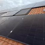
In rooftop PV systems, partial shading is often caused by chimneys, ventilation pipes, antennas, parapets, nearby buildings, trees, fallen leaves, snow or bird droppings. The key issue is not only the size of the shadow, but also its position, duration and the electrical section it affects.

Key point: managing partial shading requires looking at module layout, wiring, MPPT configuration, module structure and maintenance together. ombrage-partiel-panneau-photovoltaique-perte-puissance   

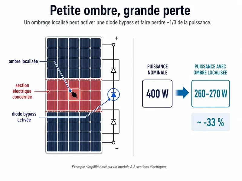
1. Why Can a Small Shadow Cause Around One Third of Power Loss?

Estimating PV loss only by the shaded surface area can be misleading.

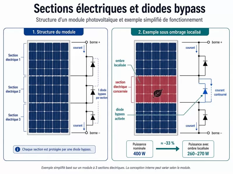
In many crystalline silicon modules, cells are connected in series and arranged into several electrical sections. A common module design includes three sections protected by three bypass diodes. The exact internal structure varies by module, but this three-section model helps explain why a small shadow can have a disproportionate impact.

When a leaf, bird dropping or chimney shadow covers one cell:

  • the current from the shaded cell decreases;
  • the cells connected in series within the same section are limited;
  • the affected section may enter reverse bias;
  • the bypass diode may activate when the required conditions are reached;
  • the module continues to operate, but the bypassed section produces much less power.

Conclusion: in a typical module with three electrical sections, if a small shadow triggers the bypass of one section, the loss may not be just a few percent. It may approach the loss of one full section, or roughly one third of the module’s power.

For a 400 W module, this may correspond, in a simplified example, to an output of around 260–270 W. The actual result depends on the module design, the shadow position, the module orientation and the inverter configuration.

sections-electriques-diodes-bypass-module-photovoltaique

2. Why Does Horizontal Shading Require Special Attention?

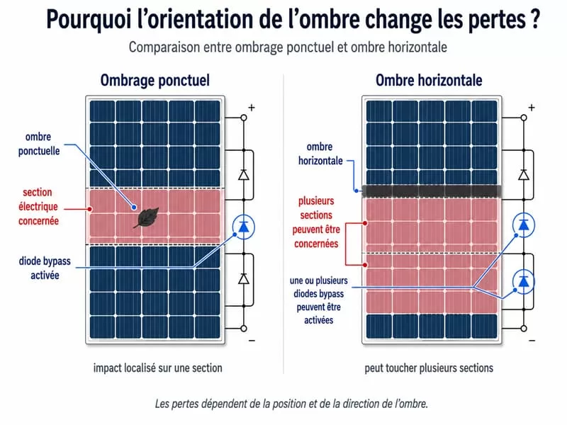
The direction of the shadow matters as much as its surface area.

A point shadow, such as a leaf or bird dropping, often affects a local area. A horizontal shadow can be more problematic because it may sweep across several cells or electrical sections, especially when it crosses the lower edge of the module.

On flat roofs, solar carports, ground-mounted systems and commercial rooftops, this type of shading often appears when the sun is low. One row of modules may cast a shadow on the next row, especially if the row spacing is too narrow.

Recommendation: address horizontal shading first through layout design, row spacing and module orientation. It is often better to install slightly fewer modules than to place panels in a recurring shaded zone.

ombrage-ponctuel-ombre-horizontale-panneau-solaire

3. Hot Spot Effect: When a Cell Becomes a Load

Partial shading does not only reduce production. It can also affect module lifetime.

Under normal operation, a photovoltaic cell generates electricity. When it is heavily shaded, it may no longer produce enough current. If the other cells in the same series circuit continue producing, the shaded cell may enter reverse bias.

It can then behave like a load, dissipating energy as heat. This phenomenon is known as a photovoltaic hot spot.

Repeated hot spots may create several risks:

Affected area

Possible risk

Photovoltaic cell

Local overheating, worsening of microcracks

EVA encapsulant

Yellowing, ageing, loss of transparency

Backsheet or glass

Thermal stress, reduced reliability

Ribbons and connections

Increased resistance, additional losses

Entire module

Accelerated degradation, less stable production

Conclusion: reducing shading is not only about producing more electricity. It is also a measure to protect long-term system reliability.

4. Bypass Diodes: Protecting the Module, Not Eliminating the Loss

A bypass diode is not a production-boosting device. It is primarily a protection component.

When an electrical section is affected by shading and enters reverse bias, the bypass diode can create an alternative path for the current. This helps limit local overheating.

However, the bypassed section does not continue producing normally. A bypass diode does not make shading harmless.

Installers and advanced users should check:

  • Does the shadow regularly activate a bypass diode?
  • Which electrical section is affected?
  • Does the loss repeat every day?
  • Does the shaded module penalize the whole string or the whole MPPT tracker?

5. Common Sources of Partial Shading in Rooftop PV Systems

Partial shading often comes from very specific rooftop or site details.

Shading source

Common situation

Main risk

Chimney

Residential pitched roof

Fixed shadow, especially morning and evening

Antenna / lightning rod

Residential or small commercial rooftop

Thin but repeated shadow

Ventilation pipe

Residential, commercial or industrial rooftop

Small surface, fixed position

Roof window

Pitched roof

Layout constraints

Parapet / roof edge

Flat roof, commercial building

Stronger shading when the sun is low

Trees and vegetation

Residential, agricultural or commercial site

Seasonal and variable shadow

Row-to-row shading

Flat roof, carport, ground-mounted system

Recurring loss if spacing is insufficient

Leaves, snow, bird droppings

Seasonal or exposed environments

Small area but hot spot risk

Key point: a small fixed and recurring shadow can be more problematic than a large occasional shadow.

6. How Can You Tell If Shading Is Already Affecting Production?

6.1 Check the Production Curve

A repeated drop at the same time of day may indicate fixed shading.

  • Morning drop: tree, chimney or antenna on the east side.
  • Late-afternoon drop: neighbouring building, adjacent roof or tree on the west side.
  • Greater seasonal losses: low sun angle, parapet or row-to-row shading.

6.2 Inspect the Module Surface

Bird droppings, fallen leaves, snow deposits, mud bands and local dirt can create persistent shading.

On low-tilt modules, rainwater removes deposits less effectively. The lower edge may accumulate a dirt band that affects the same cells repeatedly.

6.3 Analyse the Electrical Grouping

Modules with different orientations, tilt angles or shading conditions should not be placed on the same MPPT tracker without careful design.

A weaker group can force the rest of the circuit to operate at a less favourable point.

7. First Solution: Optimise the Layout Before Adding Hardware

The most effective shading solution often begins before installation.

Before choosing an optimizer or microinverter, check:

  • fixed shaded areas;
  • chimneys, parapets, ventilation pipes and antennas;
  • row spacing;
  • seasonal shadow movement;
  • portrait or landscape module orientation;
  • separation between shaded and unshaded zones.

Design principle: avoid placing a module in a recurring shaded area just to increase installed capacity.


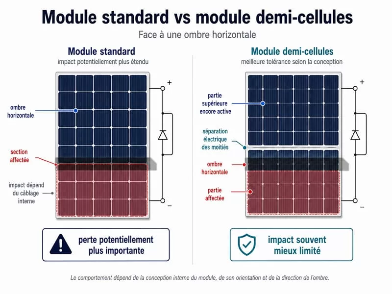
8. Half-Cell Modules: Better Management of Certain Horizontal Shadows

Half-cell modules divide each cell into two and reorganise the internal circuit. They often create more distinct upper and lower electrical areas.

In some horizontal shading situations, such as when a front row casts a shadow on the lower edge of a module, the lower part may be affected while the upper part can continue producing.

This does not mean that a half-cell module is immune to shading. The result depends on the internal design, module orientation, bypass diodes and MPPT tracker.

Suitable cases:

  • light horizontal shading;
  • row-to-row shading risk;
  • partially shaded roof edges;
  • residential or commercial projects seeking more stable output.

module-standard-vs-demi-cellules-ombre-horizontale

9. Multi-Cut Modules: More Refined Current Paths

Multi-cut modules, such as third-cut or other advanced cell-cut designs, go further than half-cell designs.

By dividing cells into smaller units, they reduce the current of each sub-cell. This can limit certain resistive losses and reduce local thermal stress.

For high-power modules, the value is not only higher power density. It also lies in more refined current management.

However, the logic should not be oversimplified: more cuts do not automatically mean better shading tolerance. Performance also depends on internal wiring, encapsulation quality, bypass diode layout and system design.

10. IBC Modules: Efficiency, Aesthetics and Low-Light Performance

IBC, or Interdigitated Back Contact, cells move the electrical contacts to the rear of the cell. The front side therefore has no visible metal grid lines.

This structure reduces shading caused by front metal contacts, increases the active light-receiving area and provides a more uniform appearance.

For projects where roof aesthetics, limited space or a uniform full-black appearance matter, IBC modules can be a relevant option. They are also useful when high power per square metre is required.

However, IBC modules do not replace proper shading management. A chimney, tree, leaf or bird dropping can still reduce output. In cases of significant shading, proper MPPT grouping, optimizers or microinverters should also be considered.


11. Multiple MPPT: Separating Roof Zones

An inverter with multiple MPPTs allows different module zones to operate at their own maximum power points.

This is useful when modules do not share the same conditions:

  • east-west roof;
  • multiple roof planes;
  • one zone with fixed shading;
  • commercial building with different shading zones;
  • modules with different tilt angles or orientations.

Key point: multiple MPPTs do not remove the shadow, but they reduce the risk that a weaker zone penalises a healthier one.


12. Power Optimizers: Isolating a Few Weak Modules

Power optimizers are usually installed near the modules. They allow each equipped module to adjust its operating point more independently.

They are especially useful when only a small number of modules are affected by fixed shading, such as a chimney, antenna, tree or roof element.

Their advantage is that they reduce the impact of weak modules on the rest of the string and provide more detailed monitoring. Their limitation is added system complexity: more components, more connections and more points to monitor.

Suitable cases:

  • fixed shading on a few modules;
  • chimney or antenna that cannot be avoided;
  • module-level monitoring requirements;
  • generally good roof conditions with a few critical areas.

13. Microinverters: For Complex Roofs and Irregular Shading

Microinverters convert DC to AC directly at the module level.

Each panel therefore operates more independently. If one module is shaded, it affects the other modules much less than in a conventional string system.

They are suitable for complex residential roofs:

  • small separate installation areas;
  • multiple orientations;
  • irregular shading;
  • possible future expansion;
  • need for module-level monitoring.

The cost is generally higher and the number of rooftop components increases. Microinverters are therefore not the default solution for every installation, but they are a relevant option for complex roofs.

14. Which Solution Should You Choose?

Roof situation

Preferred solution

Decision logic

Single orientation, little or no shading

Proper layout + half-cell or multi-cut modules

Avoid unnecessary complexity

Flat roof with row-to-row shading risk

Spacing + orientation choice + separate MPPTs

Solve the physical shading first

One or two modules affected by a chimney

Power optimizers

Isolate weak modules

Multi-plane or east-west roof

Multiple MPPTs or microinverters

Manage zones separately

Irregular shading and very complex roof

Microinverters

Make modules more independent

Aesthetic requirement or limited roof area

IBC or high-efficiency full-black modules

Maximise output per square metre

Leaves, bird droppings, snow or local dirt

Maintenance + production monitoring

Avoid recurring hot spots

solution-ombrage-photovoltaique-mppt-optimiseurs-micro-onduleurs

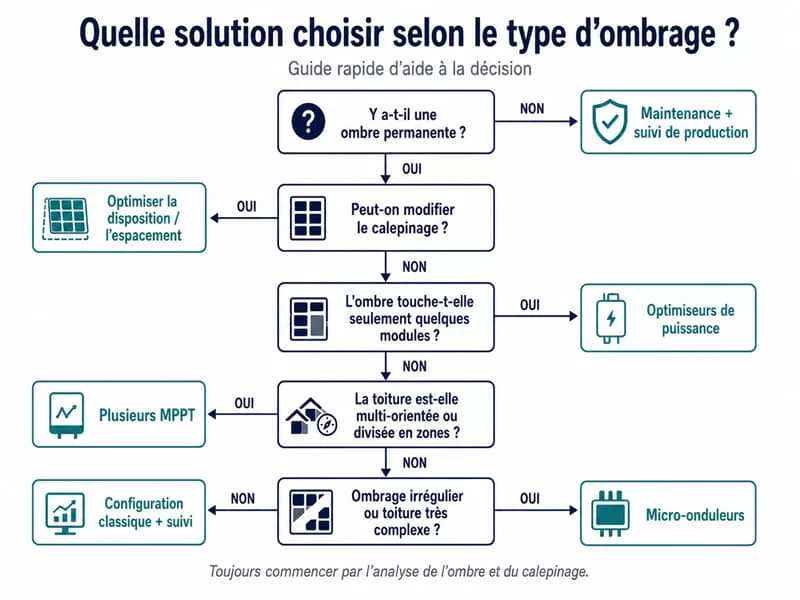
Recommended decision order:

Identify whether the shadow is permanent or temporary.

Optimise layout and spacing.

Separate zones by MPPT if conditions differ.

Use optimizers or microinverters if the shadow cannot be avoided.

Choose an appropriate module structure: half-cell, multi-cut, IBC or another high-efficiency technology.

15. Checklist Before Installation

Before installing or modifying a photovoltaic system, check:

  1. Is there a chimney, antenna, ventilation pipe, lightning rod, roof window or parapet?
  2. Will nearby trees create more shade in spring or summer?
  3. Does the shadow reach the lower edge of the modules in the morning or evening?
  4. Does the site create row-to-row shading when the sun is low?
  5. Has row spacing on a flat roof been checked for low sun angles?
  6. Can leaves, bird droppings or snow remain in the same place?
  7. Are modules with different orientations separated by MPPT?
  8. Are optimizers or microinverters necessary?
  9. Is the module structure suitable for light shading or local soiling?
  10. Does the system allow string-level or module-level monitoring?

Reference Sources
Comment produire de l’électricité chez soi — ADEME
https://agirpourlatransition.ademe.fr/particuliers/amenager-maison/renover/produire-electricite-chez-soi
Rôles des diodes by-pass présentes sur les modules photovoltaïques — GuideNR
https://www.photovoltaique.guidenr.fr/informations_techniques/conception-photovoltaique-raccordee-reseau/diode-by-pass.php
Les Effets d’ombrage sur un panneau — Oscaro Power
https://guide.oscaro-power.com/fr-FR/les-effets-dombrage-sur-un-panneau-869218
The Impact of Shading on a PV System — Fronius
https://www.fronius.com/en/solar-energy/installers-partners/info-centre/white-papers/the-impact-of-shading-on-a-pv-system
Shade encroaching on PV systems — Fronius
https://blog.fronius.com/solar-energy/en/know-how/shade-encroaching-on-pv-systems/
Optimiseurs de Puissance Résidentiels — SolarEdge
https://www.solaredge.com/fr/produits/residentiels/optimiseur-puissance-serie-s
Microinverters — Enphase
https://enphase.com/en-us/installers/microinverters

Comments

No comments yet. Why don’t you start the discussion?

Leave a Reply

Your email address will not be published. Required fields are marked *