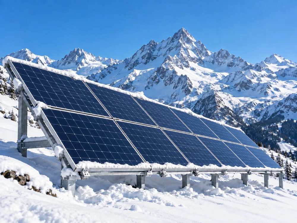
For PV projects in Alpine and other high-snow-load regions in Europe, selecting a module based only on a “5400 Pa” rating or a 30 mm vs 35 mm frame height is not enough.
A more reliable approach is to first determine the project-specific snow load according to EN 1991-1-3 (Eurocode 1) and the applicable National Annex, and then verify the module’s allowable design load under the intended mounting configuration.
For EPCs and project developers, the selection process should follow this logic:
Site snow load → Module design load → Module structure → Clamp zone → Mounting system → Roof or supporting structure
Frame height influences structural stiffness, but glass construction, module dimensions, clamp positions and rail spacing can also significantly affect the mechanical behaviour of a PV module.
The second-generation Eurocode includes specific snow-load cases for flat roofs with tilted solar or photovoltaic panels, reflecting the fact that PV arrays can themselves influence snow distribution on a roof. Eurocodes
Table of Contents
- What Does a 5400 Pa Load Rating Actually Mean?
- Why Is 5400 Pa Alone Not Enough for High-Snow-Load Projects?
- What Is the Difference Between 30 mm and 35 mm Module Frames?
- Why Do Glass Construction and Module Size Matter?
- Why Do Clamp Zones and Mounting Rails Affect Allowable Loads?
- When Might 5400 Pa Still Be Insufficient?
- EPC Checklist for High-Snow-Load PV Projects
1. What Does a 5400 Pa Load Rating Actually Mean?
A 5400 Pa value frequently appears in PV module datasheets and qualification documents. However, it represents a mechanical load verified under defined test and mounting conditions. It should not automatically be treated as the allowable design snow load for a real project.
One important distinction is:
Design Load ≠ Test Load
Under the IEC 61215 qualification framework, the test load is typically applied with a safety factor relative to the design load. NREL summarises the relationship as:
Test Load = 1.5 × Design Load
A typical example is therefore:
3600 Pa Design Load → 5400 Pa Test Load NREL
This means that when a datasheet states 5400 Pa, an EPC should still verify:
- the allowable design load;
- the approved mounting method;
- the permitted clamp zones;
- rail positions and support spacing.
IEC 61215 is a design qualification and type-approval standard for PV modules. Passing the qualification tests demonstrates resistance to defined environmental and mechanical stresses, but it does not by itself determine the suitability of a module for every building or project condition. IEC Webstore
When reviewing modules during procurement, it is therefore better to assess:
Design Load + Mounting Method + Clamp Zone + Supporting Structure
For a broader explanation of how to review datasheets, certifications, mechanical ratings and mounting requirements before procurement, see:
How to Verify Solar Panels Before Buying: Datasheets, Certifications, Warranties and Delivery Inspection Maysun Solar
2. Why Is 5400 Pa Alone Not Enough for High-Snow-Load Projects?
High snow load is first a structural design issue, not simply a module specification.
Under EN 1991-1-3, the snow load acting on a roof depends on project-specific conditions. These may include:
- regional ground snow load;
- altitude;
- roof shape and slope;
- uneven snow accumulation;
- snow drifting;
- parapets and rooftop obstacles;
- changes in snow distribution caused by PV arrays;
- requirements defined by the applicable National Annex.
This means two projects using solar modules tested to the same 5400 Pa value may still have very different structural requirements.
The second generation of EN 1991-1-3 specifically introduces cases for flat roofs with parallel rows of tilted solar or PV panels, including the effect of panel height and snow-load distribution. Eurocodes
The first question for an EPC should therefore not be:
“Does this module have a 5400 Pa rating?”
It should be:
“What is the required design snow load for this project?”
The module and mounting configuration can then be checked against that requirement.
3. What Is the Difference Between 30 mm and 35 mm Module Frames?
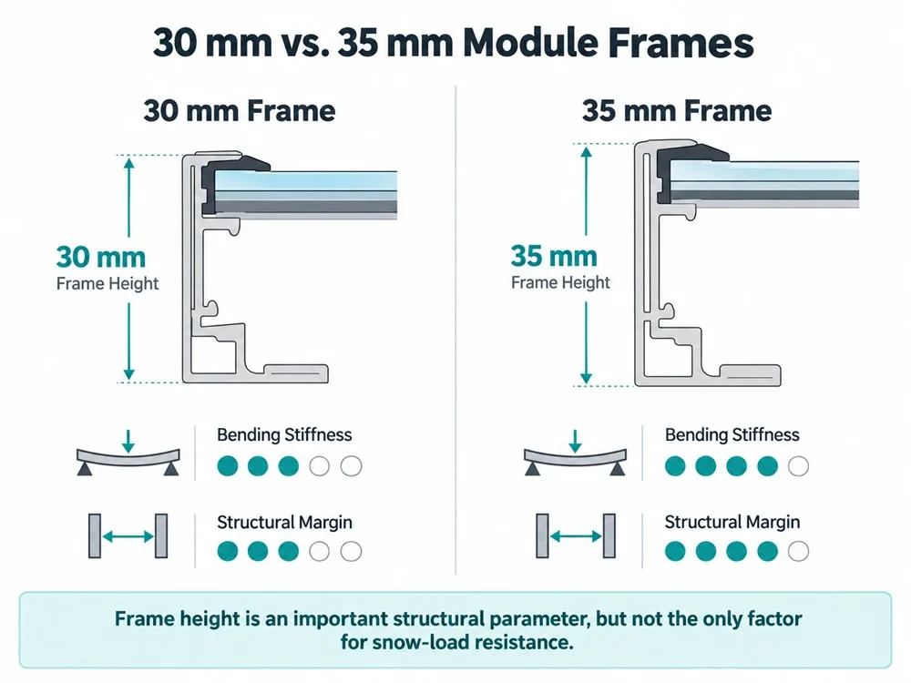
If material properties, wall thickness and profile geometry are comparable, a taller aluminium frame can generally provide greater bending stiffness.
A 35 mm frame may therefore offer more structural design margin than a lower frame.
However, this does not mean:
35 mm = high snow-load capability
30 mm = low snow-load capability
The mechanical performance of a PV module also depends on:
- aluminium profile geometry;
- frame wall thickness;
- material properties;
- module length and width;
- glass thickness;
- glass-glass or glass-backsheet construction;
- bonding between the glass and frame;
- location of support points;
- effective support span.
Frame height should therefore be treated as one structural parameter, rather than as a standalone indicator of snow-load resistance.
This distinction is increasingly important as modern modules become larger and thinner. Mechanical behaviour depends on the interaction between the module dimensions, materials and complete laminate structure—not on frame height alone. Fraunhofer ISE
4. Why Do Glass Construction and Module Size Matter?
Snow pressure is not carried only by the aluminium frame.
Mechanical loads are transferred through the complete module structure:
Glass → Encapsulation → Solar cells → Frame → Supporting structure
Fraunhofer ISE uses finite-element simulations to evaluate how module dimensions, cell size, materials and material thicknesses affect mechanical stress.
Its mechanical-load simulations include conditions ranging from 2400 Pa tensile loading to 5400 Pa compressive loading, while also evaluating module deformation and stress in the solar cells. Fraunhofer ISE
As module dimensions increase, support spacing becomes particularly important. A larger unsupported span can increase deflection in the centre of the module.
Excessive mechanical stress can also increase the risk of microcracks in solar cells. These cracks may not be visible to the naked eye and can develop into electrically inactive areas or long-term power loss.
For projects exposed to high snow loads, microcrack risk should therefore be considered as part of long-term mechanical reliability.
Microcracks On Solar Panels: Inspection & Prevention Guide 2024 Maysun Solar
For industrial rooftops, it is also important not to confuse module mechanical strength with roof load-bearing capacity.
A low-load-bearing roof should first be assessed for its remaining structural capacity. Only then should module weight, kg/m², dimensions, power density and mounting requirements be compared.
How to Choose Solar Panels for Low-Load-Bearing Industrial Roofs Maysun Solar
5. Why Do Clamp Zones and Mounting Rails Affect Allowable Loads?
For high-snow-load projects, the mounting configuration can be just as important as the frame height.
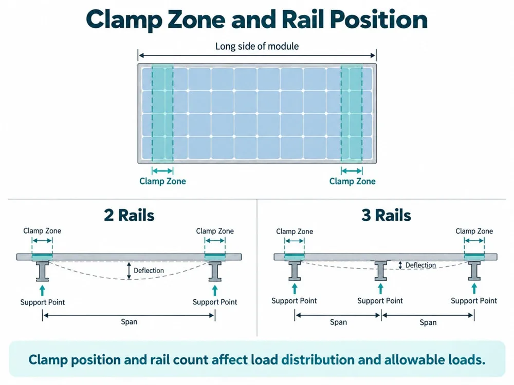
Clamp positions define the support points of the module. Changing these positions changes the effective span and the way mechanical loads are transferred through the frame and glass.
EPCs should therefore verify:
- whether clamps are positioned inside the approved clamp zones;
- the required clamp length;
- the distance between mounting rails;
- whether rails run relative to the long or short side of the module;
- whether a third supporting rail is required;
- whether clamps or mounting holes are used;
- whether the actual installation configuration is covered by the manufacturer’s validated conditions.
The importance of mounting configuration can be illustrated simply: the same module can have different allowable loads depending on whether it is supported along the long side, short side or at different clamp positions.
Adding a third rail can reduce the effective unsupported span and change the load path, helping to control module deflection.
However:
Three rails do not automatically mean a higher allowable load.
The requirement for additional support must always be determined from the specific module model, its approved mounting configuration and the structural calculation of the project.
The applicable mounting methods and installation requirements for Maysun Solar modules can be checked in the corresponding installation manuals:
Maysun Solar Installation Manuals Maysun Solar
6. When Might 5400 Pa Still Be Insufficient?
5400 Pa is not a universal threshold for every high-snow-load PV project.
More detailed structural assessment may be required in situations such as:
- high-altitude locations with high regional snow loads;
- snow drifting around parapets, ridges or rooftop equipment;
- local snow accumulation significantly above average roof loading;
- tilted PV arrays that change snow distribution;
- large-format modules with greater support spans;
- project requirements exceeding standard mounting conditions;
- higher requirements defined by the relevant National Annex;
- unusual roof or supporting-structure geometry.
In these cases, the solution should not simply be to search for a module with the highest possible Pa value.
The engineering sequence should instead be:
Project Design Load → Allowable Module Design Load → Mounting Method → Supporting Structure
Snow is also rarely the only environmental action that needs consideration. Commercial and industrial PV systems may simultaneously face wind pressure and uplift, hail, large temperature variations and other climate-related stresses.
For projects that require a broader assessment of these conditions, see:
Structural Risks and Component Adaptation Strategies for Commercial PV Deployment under Extreme Weather Conditions Maysun Solar
7. EPC Checklist for High-Snow-Load PV Projects
| Check | What Should Be Verified? |
| Site snow load | EN 1991-1-3 + applicable National Annex |
| Design Load | Allowable module design load |
| Test Load | Mechanical qualification test conditions |
| Module frame | Height, wall thickness and profile geometry |
| Glass | Thickness and glass construction |
| Module dimensions | Length, width and effective support span |
| Clamp Zone | Whether clamps are inside approved areas |
| Mounting rails | Number, orientation and position |
| Mounting method | Whether the configuration is approved for the module |
| Supporting system | Rails, fasteners and connections |
| Building structure | Whether the roof or supporting structure meets the required design load |
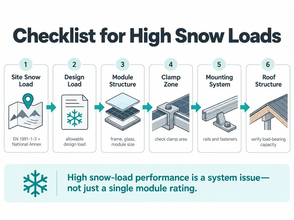
Conclusion: Snow-Load Resistance Is a System Property, Not a Single Module Number
For PV projects in high-snow-load regions, neither 5400 Pa nor a 30 mm or 35 mm frame can independently determine whether a module is suitable.
A 35 mm frame may provide greater structural design margin, but the actual allowable mechanical load also depends on:
Glass Construction + Module Dimensions + Clamp Zone + Support Span + Mounting Method
For EPCs, a more reliable selection process is:
Site Snow Load
→ Module Design Load
→ Module Structure
→ Mounting Method
→ Supporting Structure
Only when the project load, module design and mounting system are correctly matched does a mechanical load value such as 5400 Pa have meaningful value for the project.
Sources and Technical References
- International Electrotechnical Commission (IEC)
IEC 61215-1:2021 — Terrestrial photovoltaic (PV) modules – Design qualification and type approval – Part 1: Test requirements
Defines the general requirements for PV module design qualification and type approval. IEC Webstore
IEC 61215-1:2021 – Official IEC Source - International Electrotechnical Commission (IEC)
IEC 61215-2:2021 — Terrestrial photovoltaic (PV) modules – Design qualification and type approval – Part 2: Test procedures
Defines PV module qualification test procedures, including mechanical and dynamic mechanical load testing. IEC Webstore
IEC 61215-2:2021 – Official IEC Source - National Renewable Energy Laboratory (NREL)
Growing Panes: Investigating the PV Technology Trends Behind Frequent Early Failures in Modern Glass-Glass Modules
Summarises the IEC 61215:2021 relationship between design load and qualification test load, including the 1.5 test safety factor. NREL
NREL – Growing Panes - European Commission — Joint Research Centre (JRC)
The Second Generation Eurocodes: EN 1991-1-3 Snow Load
Provides updated snow-load design examples, including flat roofs with tilted solar and photovoltaic panels. Eurocodes
European Commission JRC – EN 1991-1-3 Snow Load
5. Fraunhofer Institute for Solar Energy Systems ISE
Thermo-Mechanical Simulations
Uses FEM simulations to study module deformation, mechanical stresses and solar-cell fracture risk under different module dimensions, materials and mechanical loads. Fraunhofer ISE
Fraunhofer ISE – Thermo-Mechanical Simulations