2. Four indicators to compare before selecting a module
2.1 Weight per square metre in kg/m²
Solar modules vary considerably in size. Comparing only the weight of one panel can therefore be misleading.
The first calculation should be:
Module weight per square metre = module weight ÷ module area
At project-design level, a second figure is even more important:
System weight per square metre = total weight of modules, rails, fasteners and ballast ÷ actual covered area
This provides a more realistic indication of the permanent load added to the roof.
2.2 Power density in W/m²
A low-load-bearing roof must limit additional weight while making efficient use of the available surface.
A high-efficiency module can install more capacity within a given area. It may also reduce the number of modules, electrical connections and some mounting components.
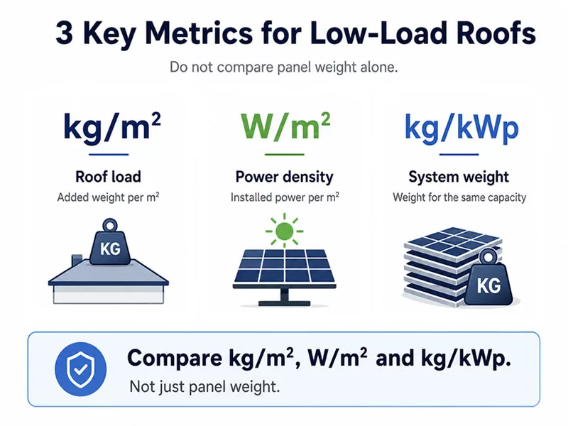
Three indicators should ideally be compared:
Indicator | Main purpose |
kg/m² | Shows how much weight is added per square metre |
W/m² | Shows how much rated power can be installed per square metre |
kg/kWp | Shows how much system weight is required for a given capacity |
For a load-restricted roof, kg/kWp may provide a more useful comparison than the weight of an individual module.
2.3 Module dimensions and layout flexibility
A large-format module may offer high rated power, but it can also increase:
- the number of people needed for handling;
- lifting complexity;
- rooftop installation risks;
- the surface exposed to wind;
- constraints relating to clamping zones and rail positions.
On roofs with skylights, smoke vents and other equipment, oversized modules may reduce layout flexibility.
If the permitted module clamping zones do not align with the purlins, additional rails or support members may be required. The weight saved by using fewer modules may then be offset by a heavier mounting structure.
The comparison should therefore be based on total capacity after a realistic roof layout, not solely on the wattage stated on the datasheet.
2.4 Mechanical loads, fire performance and technical approvals
The front- and rear-side mechanical load ratings on a module datasheet describe the module’s resistance under defined test conditions.
They do not indicate how much additional load the building roof can support.
The project should also verify:
- compatibility between the module and mounting system;
- suitability of the fasteners for the roof covering;
- compatibility with waterproofing and insulation;
- fire performance;
- availability of technical and insurance documentation.
For projects in France, the applicable Avis Technique, ATEx or another relevant technical assessment should also be checked.
CSTB guidance recommends treating the module, mounting system, roof covering and supporting structure as one complete technical system. [2][3]
3. Which solar panels suit low-load-bearing industrial roofs?
For most industrial roofs with limited load capacity, flexible modules should not automatically be the first option.
It is often more practical to begin with rigid crystalline-silicon modules that combine:
- high power density;
- manageable dimensions;
- controlled weight;
- compatibility with a proven lightweight mounting system.
Standard-size modules with high power density
These modules can suit roofs with limited spare capacity but a sound primary structure.
Compared with very large modules, standard-size products are usually easier to arrange around skylights, smoke vents and other rooftop equipment. They are also easier to handle, install and replace.
IBC back-contact modules can be considered within this category.
In an IBC cell, the positive and negative metal contacts are moved to the rear. The front surface therefore has no conventional metal grid. Fraunhofer ISE research notes that this metal-free front side reduces shading losses during illumination. [4]
For a low-load-bearing roof, the potential value of IBC includes:
- high power density within a standard format;
- fewer modules to reach a given system capacity;
- the possibility of reducing clamps, connections and some cable runs;
- greater flexibility on complex roofs;
- in some products, a glass-backsheet construction that weighs less than a similar-size glass-glass module.
IBC should not, however, be described as inherently lightweight in every case. Its suitability must be confirmed by comparing the complete system in kg/m² and kg/kWp.
Architectural appearance and visual integration of IBC modules
IBC can also provide architectural benefits.
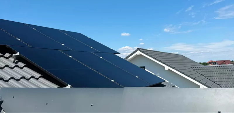
Because the metal electrodes and interconnection ribbons are positioned on the rear, the visible module surface is more uniform. This makes it easier to create a consistent all-black appearance with fewer visible interruptions.
Compared with modules that show silver grid lines and ribbons on the front, IBC modules can reduce local metallic highlights and produce a more visually consistent array.
This can be useful for:
- urban industrial buildings;
- commercial properties;
- offices and company headquarters;
- projects close to residential areas;
- buildings with specific architectural requirements.
A more uniform appearance can help integrate the PV system with the building envelope and reduce visual disturbance.
Overall reflectance will still depend on the front glass, anti-reflective treatment, installation angle and viewing direction.
Large-format, high-power modules
Large-format modules are best suited to extensive, unobstructed roofs with reliable structural information and suitable lifting conditions.
They can reduce the number of panels and electrical connections, but the following factors still require assessment:
- individual module weight;
- handling and lifting conditions;
- wind-exposed surface area;
- purlin positions and clamping zones;
- actual roof utilisation;
- the need for additional rails.
If substantial extra support is required to align the modules with the roof structure, a large-format product may not reduce total system weight.
Lightweight or flexible modules
Flexible modules should not be treated as the standard solution for ordinary residential or industrial roofs.
They are more relevant when the remaining structural capacity is extremely limited and conventional glass modules cannot be installed. Examples may include certain industrial membrane roofs, curved surfaces or buildings where conventional mechanical mounting is not possible.
In these cases, the module, adhesive system and roof membrane must be assessed as one complete assembly.
Important factors include:
- fire performance;
- heat dissipation;
- ultraviolet ageing;
- long-term adhesive strength;
- compatibility with the roof membrane;
- replacement and maintenance options.
Where a roof can accommodate rigid high-power-density modules with a lightweight mounting system, that option should normally be compared before moving to a specialised flexible solution.
Module type | Main advantage | Main limitation | Suitable application |
IBC or another standard high-power-density module | High output, manageable dimensions and consistent appearance | Complete system load must still be calculated | Roofs limited by both load and available area |
Large-format high-power module | Fewer modules and electrical connections | Higher individual weight and greater handling and wind requirements | Large, unobstructed roofs with known structural conditions |
Special lightweight module | Significantly lower module weight | Certification, thermal behaviour and durability require close assessment | Roofs where conventional rigid modules cannot be used |
5. A five-step selection process
Step 1: inspect the roof and supporting structure
Collect information on:
- structural drawings;
- roof covering;
- purlin spacing;
- previous modifications;
- corrosion, deformation and water ingress;
- existing rooftop equipment.
Step 2: calculate the remaining load-bearing capacity
A qualified structural engineer should determine how much additional load the roof can safely support in its current condition.
A solar-module datasheet cannot replace a structural assessment of the building.
Step 3: calculate the complete PV system load
The calculation should include:
- modules;
- rails and mounting components;
- fasteners;
- ballast;
- cable trays;
- construction and maintenance loads;
- concentrated loads.
Step 4: compare several system options
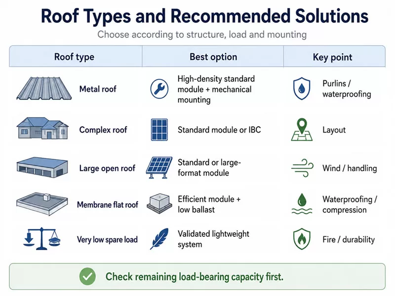
Roof condition | Option to assess first | Main risks |
Trapezoidal sheet-metal roof | Standard high-power-density module with mechanical mounting | Purlin positions, water ingress and corrosion |
Complex roof with extensive equipment | Standard-size IBC or another high-efficiency module | Layout efficiency and fixing points |
Large, open industrial roof | Standard or large-format high-power module | Wind, handling and concentrated loads |
Flat membrane roof | High-efficiency module with low-ballast or lightweight mounting | Waterproofing compatibility and insulation compression |
Roof with extremely limited spare capacity | Technically validated lightweight system | Fire, thermal behaviour and long-term bonding |
Roof approaching refurbishment | Refurbish or reinforce before selecting modules | Removal and reinstallation costs |
Step 5: compare whole-life costs
Module purchase price is only one part of the project.
The assessment should also include:
- actual installable capacity;
- expected annual energy yield;
- structural reinforcement costs;
- lifting and installation costs;
- remaining roof life;
- maintenance and replacement;
- long-term project return.
Four mistakes should be avoided:
- Comparing only individual module weight while ignoring rails and ballast.
- Automatically selecting the highest-wattage or largest module.
- Confusing module mechanical load ratings with the roof’s structural capacity.
- Ignoring the remaining life of the roof and future refurbishment costs.