
Table of Contents
Introduction
As renewable energy continues to expand, solar panels have become an increasingly popular clean and sustainable option. With the wider adoption of photovoltaic technology, more users are also becoming aware of the common solar panel issues and potential risks associated with long-term operation.
To ensure that a PV system remains stable and efficient throughout its lifetime, understanding these problems — and knowing how to address them — is essential. This article outlines some of the typical situations that may arise during the use of solar panels and highlights the key factors in selecting reliable solar PV modules, helping improve overall system performance and long-term energy yield.
What are the most common faults and potential issues in solar panels?
Although these problems may appear diverse, most common solar panel issues stem from material ageing, environmental stress, abnormal current pathways, or improper installation conditions. Understanding the root causes helps prevent failures early during module selection and system design.
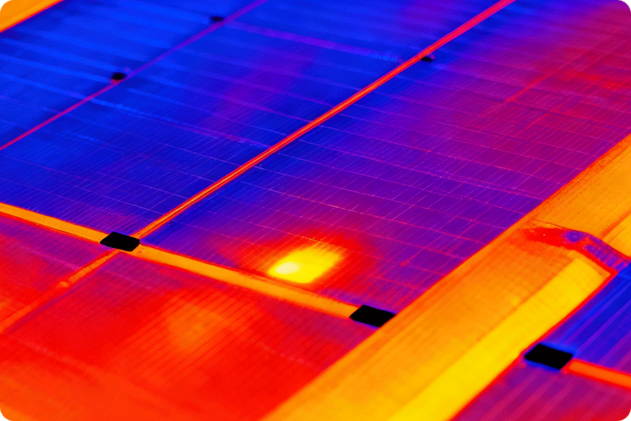
Hotspot effect
The hotspot effect is essentially a localised thermal runaway caused by accumulated I²R losses. When a cell develops microcracks, weak solder joints or partial shading, the series resistance (Rs) increases. As the string must carry the same current, the high-resistance area is forced to dissipate additional energy. Under a typical operating current of 8–10A, even a 20–40 mΩ rise in local series resistance can raise the temperature by 25–45°C, pushing materials into an accelerated ageing state.
When temperatures reach 80–110°C, the following irreversible failure modes often appear:
-
EVA oxidation → faster yellowing and reduced light transmission
-
Silver gridlines / solder ribbon annealing → metal migration and further resistance increase
-
Uneven stress in glass/cell → visible or latent cracks induced by mechanical strain
When partial shading occurs, the bypass diode will switch on prematurely, indicating that the substring has entered an abnormal operating state. Frequent thermal cycling (on/off switching) causes diode solder fatigue and encapsulation stress accumulation, allowing the hotspot region to expand over time. Thermal imaging will show increasingly prominent hot areas.
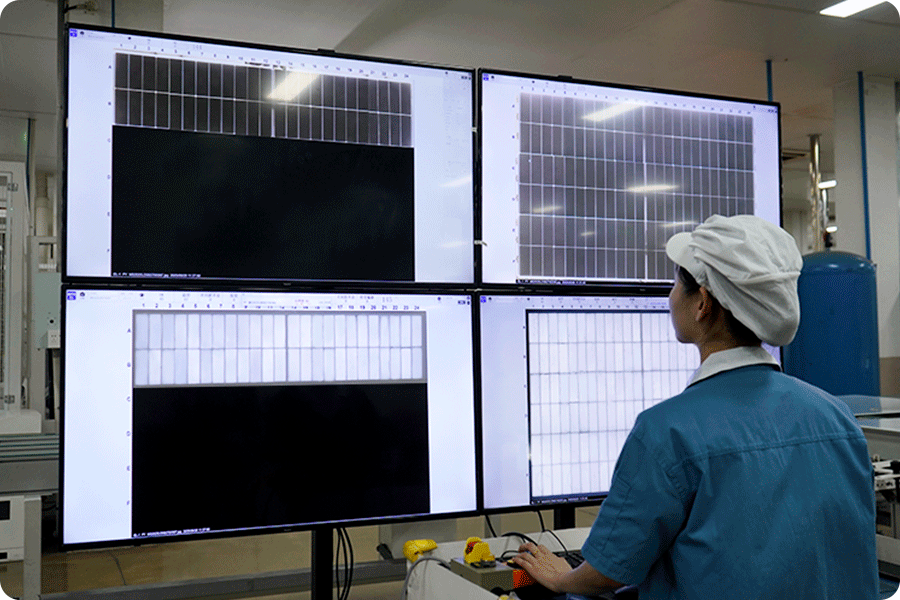
Microcracks and snail trails
Microcracks usually result from external impact, manufacturing stress or temperature cycling. As wafer thickness has generally reduced to 160–170 μm, cells are more prone to subtle, invisible cracks during sorting, soldering, transport and installation. These cracks reduce local carrier transport capability, increasing series resistance (Rs) and causing minor power loss.
Snail trails are the visible expression of microcracks in humid environments, caused by silver electrode migration or sulphidation around the crack edges. They indicate weakened material integrity within the solar PV modules. With continued thermal cycling, cracks may propagate further, leading to FF (fill factor) reduction, uneven output and lower long-term energy yield.
The core risk of microcracks lies in undermining long-term stability, making proper packing, transport and installation essential to prevent initial mechanical damage.
Internal module defects (solder failures, junction box issues, encapsulation defects)
Internal defects typically arise from accumulated mechanical stress, material fatigue or seal failure. Common forms include solder-joint detachment, ribbon breakage, junction box water ingress and encapsulant delamination.
During soldering, joints experience instantaneous thermal shock of around 140–160°C. Uneven cooling or external stress can later lead to metal fatigue. Over years of operation, a module may undergo 600–900 day–night thermal cycles annually (with 30–45°C temperature swings), causing solder interface resistance to rise by 2–5 mΩ — enough to disturb current flow stability.
If a junction box suffers seal degradation or microcracks in the backsheet, moisture can spread along the ribbons, reducing insulation resistance from GΩ-level to hundreds of MΩ and increasing corrosion and leakage risks. Early delamination between EVA/POE and glass or backsheet weakens mechanical support for the cells and ribbons, making intermittent electrical contact more likely during temperature cycling. This manifests as IV curve instability, rising series resistance and long-term output fluctuations.
Such internal defects break the continuity of the current path and represent irreversible performance loss. Careful handling during packaging, shipping, mounting and operation is essential to minimise thermal and mechanical stress and ensure the junction box and encapsulation remain intact.
Performance degradation (LID / LeTID / PID)
Performance degradation occurs for different reasons:
-
LID (Light-Induced Degradation) typically appears in the early stage of strong light exposure, with a typical loss of 0.8–1.5%, caused by boron–oxygen complexes reducing carrier lifetime.
-
LeTID (Light and Elevated Temperature Induced Degradation) occurs under high temperature + electrical load, with peak losses reaching 3–6%, common in humid climates or on dark-coloured rooftops.
-
PID (Potential-Induced Degradation) relates to system voltage and humidity. It is more likely in 1500V systems or damp environments, with local degradation sometimes exceeding 10%.
The core issue is not the one-time loss but the long-term shift of the power output curve. Technologies susceptible to higher degradation will exhibit persistently lower effective energy yield from year 3 to year 8, impacting full lifecycle returns.
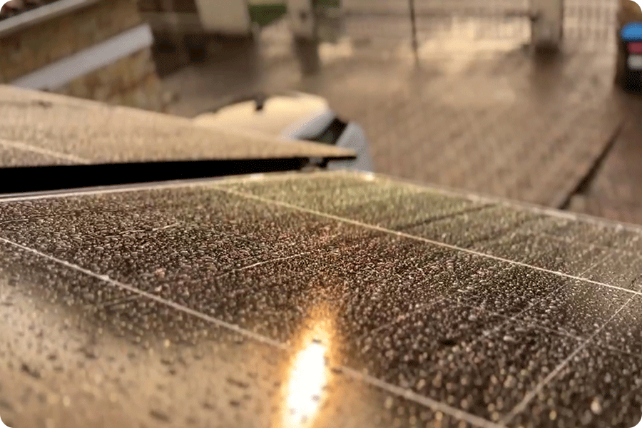
Backsheet cracking and moisture ingress
The backsheet undergoes continuous UV exposure, temperature cycling and mechanical stress outdoors, making it prone to micro-cracks as it ages. Once compromised, moisture can enter the laminated structure, corroding ribbons and electrical connections while weakening the encapsulant barrier.
DNV and NREL damp-heat testing shows that after moisture ingress, insulation resistance can fall from GΩ to hundreds of MΩ, significantly reducing dielectric strength and increasing the likelihood of PID acceleration and local leakage.
This degradation is often hard to detect in the early stage but later appears as power loss and expanding failure zones. Therefore, the backsheet grade should be considered during module selection, and regular inspections are needed to detect cracks or moisture ingress.
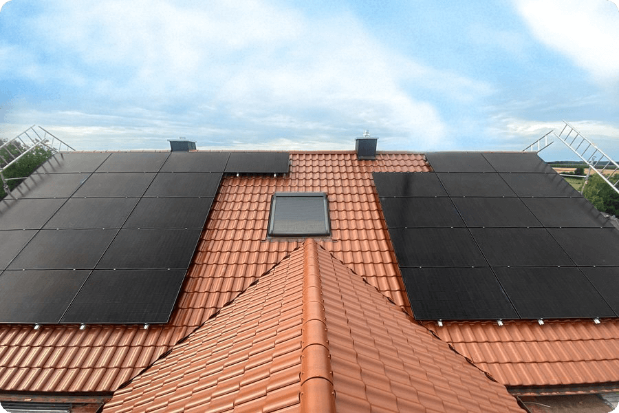
Installation-related issues
Improper installation is the source of many solar module troubleshooting scenarios, including incorrect tilt angle, fixed shading objects and insufficient ventilation. Each of these factors affects thermal management, irradiance capture and current stability.
-
Tilt and orientation mismatch
If the tilt is too low or too steep, or the orientation deviates from the optimal direction, annual irradiance decreases. In Southern Europe, a 10° deviation from south can reduce annual yield by around 2–4% (PVGIS data). -
Shading causing premature bypass activation
Chimneys, trees or similar obstructions can cast partial shadows, pushing the shaded substring into an “abnormal operating region” and triggering the bypass diode. Fraunhofer ISE tests show that even 3–5% shading can reduce substring output by 15–25% and significantly increase hotspot risk. -
Poor ventilation causing temperature rise
Insufficient clearance between module and roof reduces cooling efficiency, keeping operating temperatures higher. According to NREL and Sandia:-
Each 1°C rise leads to a 0.30–0.45% power reduction
-
If the ventilation gap is below 6–8 cm, backsheet temperature may increase by an additional 8–12°C
-
Recommended gap: ≥ 10–15 cm
-
These factors collectively reduce daily yield and widen the gap between design output and actual performance. Correct tilt, avoiding fixed shading, and ensuring adequate ventilation are essential for maintaining safe operating temperatures of solar PV modules.
Environmental factors
Solar panels are continuously exposed to outdoor conditions, making them vulnerable to climate and seasonal variations. Without considering local conditions during design, ageing may accelerate.
-
High temperatures can raise module operating temperatures to 60–75°C in summer. Each 10°C increase may reduce power by 3–4.5%, and prolonged heat exposure may worsen LeTID and encapsulation ageing.
-
Snow and wind loads during winter or extreme weather add mechanical stress. Poor layout or insufficient mounting strength can lead to microcracks, frame deformation or even module breakage. IEC 61215 load tests can withstand 2400–5400 Pa, but poor installation can cause far higher local stress.
-
Salt mist, humidity and strong UV accelerate ageing in backsheets, solder joints and encapsulants, reducing insulation resistance — often from GΩ to hundreds of MΩ — and increasing PID risk.
Environmental factors cannot be avoided, but with proper module selection (e.g., double-glass structure, high-grade weather-resistant materials) and installation adapted to the local climate, these hidden losses can be significantly reduced.
Solutions: Choosing Reliable Solar Panels
Having understood the mechanisms behind common solar panel issues, the next and more critical step is to reduce these risks through the right module structure, cell technology and system design. The following three dimensions explain how to effectively avoid hotspots, microcracks, degradation and environmental ageing when selecting solar PV modules.
1. Choosing a reliable module structure
Module encapsulation structure
The encapsulation method determines moisture barrier capability, mechanical stability and long-term ageing performance. Double-glass solar modules offer a water vapour transmission rate (WVTR) as low as 10⁻⁶ g/m²·day, significantly outperforming traditional backsheet designs. They maintain encapsulation integrity more effectively in humid, coastal, rainy or large temperature-difference climates.
Single-glass modules are lighter (typically 3–6 kg lighter than double-glass of the same wattage), making them better suited to residential rooftops with load limitations. Bifacial modules can gain an additional 5–10% energy yield on light-coloured roofs or highly reflective ground, while also offering stronger structural stability and weather resistance.
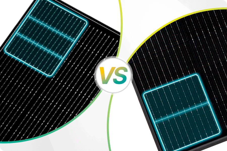
Cell process structure
The way solar cells are divided directly affects current pathways and local resistance under shading. Half-cut designs halve the current, reducing hotspot risk. In recent years, an even finer division — the 1/3-cut structure — has emerged. By dividing each cell into three smaller pieces, current is reduced and internal pathways shortened, lowering local series resistance and the resulting temperature rise. This is particularly suitable for light shading from trees, balcony railings or nearby structures.
These designs help maintain stable output under conditions of microcracks, high temperatures or partial shading, reducing the likelihood of solar module troubleshooting events.
Choosing a suitable power class for the rooftop size
Module size and wattage significantly influence layout, ventilation and loading.
-
430–460W medium-size modules suit residential rooftops and allow flexible placement.
-
550–600W and above large-format modules suit commercial and industrial rooftops, improving energy yield per area and reducing mounting system quantity.
Correctly matching module size with roof structure helps avoid overly dense layouts, insufficient ventilation or excessive mechanical load, ensuring more stable system operation.
2. Choosing cell technologies with more stable performance
Different technology routes vary in their sensitivity to degradation, temperature and shading. Selecting the right technology helps reduce hotspot formation, mitigate long-term degradation and improve system yield.
IBC: Better shading tolerance and strong low-light performance
IBC uses a back-contact design without front metal grids, reducing shading losses and improving stability under weak light, oblique irradiation and partial shading. With no front solder ribbons, IBC also suffers less power loss from microcrack-related disruptions.
In addition, IBC typically uses higher-grade wafers and superior passivation, offering lower LID/LeTID degradation and better long-term reliability. This makes it well-suited for rooftops with variable weather or higher reliability requirements across residential and commercial projects.
TOPCon: Higher efficiency and lower degradation — the mainstream choice
TOPCon introduces a tunnelling oxide layer and doped polysilicon passivation layer on the PERC base, reducing carrier recombination and lowering initial LID losses. It also offers higher module efficiency and stable performance in high-temperature and humid environments, making it one of the most widely adopted technologies.
With its typically higher bifaciality, TOPCon delivers additional yield on light-coloured roofs or reflective surfaces. Supported by a mature mass-production ecosystem, TOPCon performs reliably in damp-heat and thermal-cycling tests, making it a balanced choice for most residential and commercial projects.
HJT: Lower temperature coefficient and stronger low-light performance
HJT combines crystalline silicon with amorphous silicon thin layers, providing superior interface passivation and a temperature coefficient typically lower than conventional technologies (around −0.243%/°C). In high-temperature conditions such as summer or dark-coloured roofs, power loss is significantly reduced, ensuring more stable annual output.
HJT naturally avoids LID, shows very low LeTID risk and has stronger PID resistance due to its stable interface structure. It is therefore well-suited for metal roofs, coastal regions and high-temperature Southern European climates where strong environmental adaptation is required.
Its heterojunction and thin-film structure also make it less sensitive to mechanical stress, lowering the risk of microcracks during transport or installation and improving system reliability.
| Technology | Typical Efficiency Range | Low-Light Performance | High-Temperature Performance | Degradation Risk | Suitable Scenarios |
|---|---|---|---|---|---|
| IBC | 21.7–23.5% | ★★★★☆ | ★★★☆☆ | Low | Roofs with frequent shading or low-light conditions |
| TOPCon | 21.5–23.2% | ★★★☆☆ | ★★★★☆ | Low–Medium | General residential and commercial applications |
| HJT | 21.7–23.4% | ★★★★☆ | ★★★★★ | Very Low | High-temperature, coastal or metal-roof environments |
3. Focusing on installation quality and long-term reliability
After selecting the right structure and technology, installation quality and operating conditions are equally crucial to maintaining long-term stability. Many hotspots, leakage issues and degradation phenomena do not originate from the module itself but from tilt errors, fixed obstructions or insufficient ventilation.
Correct tilt and layout, adequate rear ventilation and avoiding permanent shading are key to keeping modules within a safe operating temperature range.
During system operation, junction boxes, sealing strips and mounting fasteners should be regularly inspected to avoid hidden losses caused by loosening, water ingress or corrosion. In regions with heavy snow, high humidity or salt mist, higher-grade mounting structures and installation methods should be used to enhance system reliability.
Beyond system-level risk control, module certification and warranty also matter. Selecting modules tested to IEC 61215 and IEC 61730, as well as appropriate fire ratings (e.g., Class A), ensures stability in mechanical load, electrical safety and building integration. Reliable manufacturers typically provide at least a 12-year product warranty and a 25-year linear power warranty, offering essential long-term assurance.
Conclusion
Issues such as hotspots, microcracks, PID and environmental ageing in solar panels ultimately arise from a combination of material characteristics, manufacturing processes and operating conditions. By selecting more reliable module structures (such as double-glass or 1/3-cut designs), choosing cell technologies suited to the project’s climate and application scenario (IBC, TOPCon or HJT), and ensuring proper installation and long-term maintenance, the vast majority of common solar panel issues can be effectively prevented.
From residential installations to commercial and industrial projects, only when module selection, system design and on-site construction are all carried out to a high standard can solar PV modules deliver stable, efficient and predictable performance throughout their entire lifecycle.
Maysun Solar is a solar module supplier focused on the European market, offering high-efficiency IBC modules, HJT modules and TOPCon modules across multiple technology routes. With stable local warehousing and supply capabilities, the company provides reliable module selection guidance for a wide range of rooftop types and application scenarios, helping projects maintain higher stability and stronger energy yields over the long term.
Reference
NREL (National Renewable Energy Laboratory). PV Module Reliability and Degradation Research. https://www.nrel.gov/pv
Fraunhofer ISE (2024). Photovoltaics Report – Key Figures and Performance Trends. https://www.ise.fraunhofer.de/en.html
Sandia National Laboratories. PV Performance Modeling Collaborative (PVPMC). https://pvpmc.sandia.gov
IEA PVPS (2023). Task 13 – Performance and Reliability of Photovoltaic Systems. https://iea-pvps.org/research-tasks/task-13/
DNV (2021). Solar Module Reliability Scorecard – PVEL Annual Results. https://www.dnv.com/services
Recommend Reading
March European Solar Industry News
This article outlines recent developments in the European solar market, including the EU cross-border solar auction scheme, structural shifts in Germany, updated GSE regulation in Italy, and the recent recovery in solar panel prices.

430–460W or 600W+? How Should You Choose Solar Panel Power for Rooftop Projects?
Compares 430–460W solar panels and 600W solar panels in C&I rooftop projects, showing that solar panel selection should prioritise roof compatibility and system stability.
Changes in the European Solar Policy and Market in 2026
Europe’s 2026 solar policy and grid changes are reshaping solar panel selection, shifting project returns towards market-driven mechanisms and highlighting the roles of TOPCon, HJT and IBC solar panels.
Why European EPCs Are Reassessing Large-Format Solar Panels
European EPCs are re-evaluating large-format solar panels. Panel size directly affects installation risk, system compatibility, and solar project ROI stability.
Do Vertical Bifacial Modules Really Deliver Additional Yield?
Vertical bifacial PV systems are gaining increasing attention across Europe. This article explores under what conditions a vertical layout can create additional value, how bifacial gain is influenced by site conditions, and which project types are best suited to this design.
Which rooftop scenarios make 700W+ solar panels a risk?
An analysis of the practical limits of 700W+ high-power solar panels on residential and commercial rooftops, and how space, load capacity, self-consumption and maintenance affect real returns.