


Efficiency: 21-22.5%
Dimensions (L × W × H): 1722 x 1134 x 30 mm
Weight: 20.8kg
Packaging:36 pieces/pallet, 936 pcs/40'HQ
Warranty: 25-year performance warranty

Efficiency: 21.7-23.1%
Dimensions (L × W × H): 1722 x 1134 x 30 mm
Weight: 20.8kg
Packaging: 36 pcs/pallet, 936 pcs/40'HQ
Warranty: 25-year product and performance warranty

Efficiency: 21.5-23.2%
Dimensions (L × W × H): 2278 x 1134 x 30 mm
Weight: 27.5 kg
Packaging: 36 pcs/pallet, 720 pcs/40'HQ
Warranty: 25-year product and performance warranty
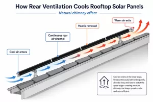
Why Do Solar Panels Lose Power in Hot Weather? How Temperature Coefficient and Roof Ventilation Affect Summer Energy Yield
Summer brings stronger sunlight and longer daylight hours, so it is normally one of the most productive seasons for a solar system. However, some system owners notice that solar panel output does not continue to rise during the hottest part of the day.
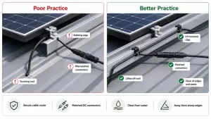
How to Design a Low-Maintenance Rooftop Solar System
Introduction A low-maintenance rooftop solar system is not created after installation. It is designed before installation. Over a 20–30 year operating life, rising O&M costs are rarely caused by dirty glass alone. They are more often caused by design decisions made at the
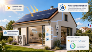
European Heatwaves and PV Self-Consumption: Why HJT Solar Modules Perform Better in Hot Summers
Across Europe, summer heatwaves are no longer just a climate or comfort issue. They are becoming an energy-use issue. During hot summer days, air conditioning, ventilation, refrigeration, office equipment and industrial cooling loads can rise exactly when rooftop solar modules are exposed to
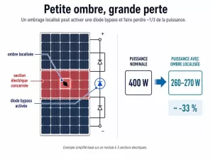
Partial Shading on Solar Panels: Why a Small Shadow Can Cause Major Power Losses
Introduction: Shading Is Not Just a Surface Area Problem In a photovoltaic system, a small shadow can be amplified by the electrical structure of the module. In a typical module with three electrical sections, a shaded area covering only a small part of
From Half-Cell to Multi-Cut: Why PV Modules Are Paying More Attention to More Segmented Circuit Design?
Table of Contents In recent years, half-cell modules have become a mainstream design in the photovoltaic market. Compared with traditional full-cell modules, half-cell technology reduces the operating current of each cell unit, lowers internal resistive losses, and improves thermal management and partial shading
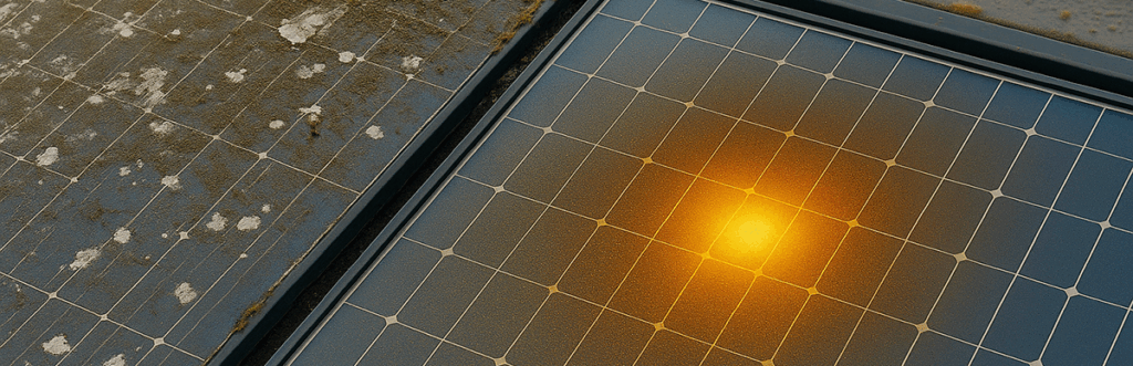
Does Summer Heat Reduce Solar Panel Efficiency? What Really Happens to PV Output
Table of Contents Many PV users notice an unusual phenomenon in summer: although sunlight is strongest at noon, the power curve shown in the monitoring app does not reach the expected peak. In contrast, on a sunny spring day, or just after a