


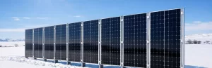
430–460W or 600W+? How Should You Choose Solar Panel Power for Rooftop Projects?
Compares 430–460W solar panels and 600W solar panels in C&I rooftop projects, showing that solar panel selection should prioritise roof compatibility and system stability.
Changes in the European Solar Policy and Market in 2026
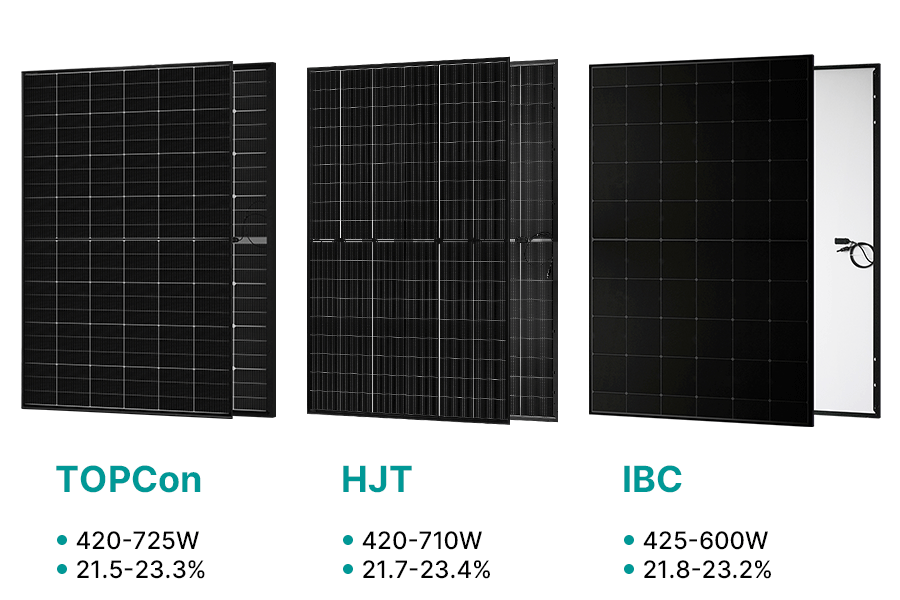
Europe’s 2026 solar policy and grid changes are reshaping solar panel selection, shifting project returns towards market-driven mechanisms and highlighting the roles of TOPCon, HJT and IBC solar panels.
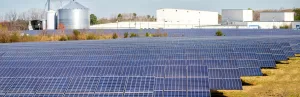
Why European EPCs Are Reassessing Large-Format Solar Panels
European EPCs are re-evaluating large-format solar panels. Panel size directly affects installation risk, system compatibility, and solar project ROI stability.
Do Vertical Bifacial Modules Really Deliver Additional Yield?
Vertical bifacial PV systems are gaining increasing attention across Europe. This article explores under what conditions a vertical layout can create additional value, how bifacial gain is influenced by site conditions, and which project types are best suited to this design.

Which rooftop scenarios make 700W+ solar panels a risk?
An analysis of the practical limits of 700W+ high-power solar panels on residential and commercial rooftops, and how space, load capacity, self-consumption and maintenance affect real returns.
February News in the Photovoltaic Industry
February overview of Europe’s photovoltaic market: module price trends, a rebound in the German PPA market, progress in Italian agrivoltaics and regulatory shifts in France, highlighting key industry signals.
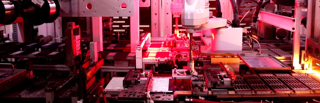
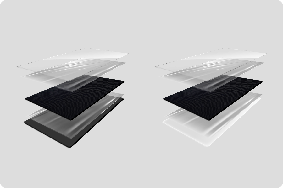
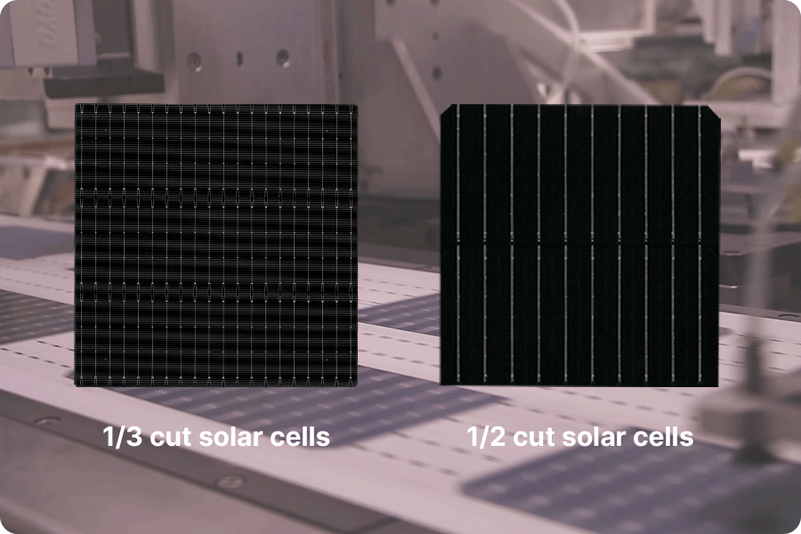
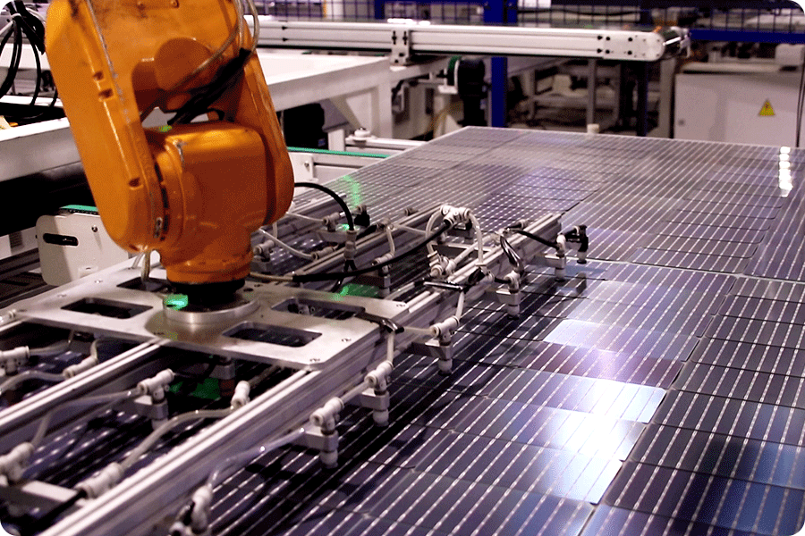
Clear overview of the manufacturing steps and, more importantly, how process control affects long-term module quality.
The explanation around EL inspection, lamination and outgoing tests is particularly useful for understanding why modules that look similar on paper can behave very differently over time.